The Problem
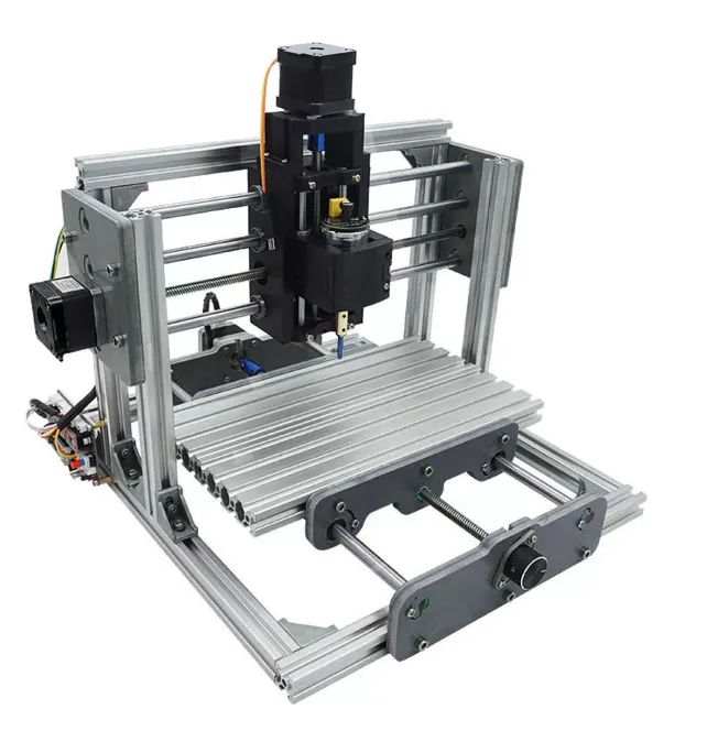
A budget desktop CNC router kit — 240×170mm travel — is adequate for foam and balsa engraving. It is not adequate for cutting wood, engineering plastics, or any non-ferrous metal. The frame itself was 2020 T-slot aluminium extrusion, but every functional mounting point was plastic: the X and Y axis motor mounts, the linear bearing mounts, the lead screw bearing blocks, the lead screw nut mounts, and the X and Y axis carriages themselves were all 3D printed. This plastic structure flexes under any meaningful cutting load. Add to that a grub-screw spindle with poor tool retention, no homing capability, and a proprietary control board with no configurability, and the machine’s limitations were systematic rather than incidental. The goal was to remove them without discarding the linear hardware, which was not the bottleneck.
Upgrade Sequence
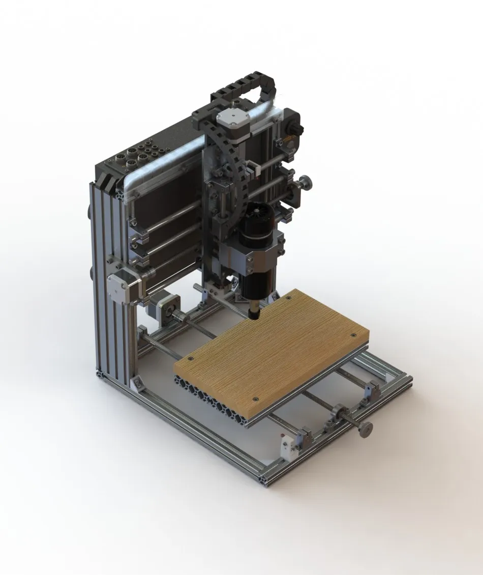
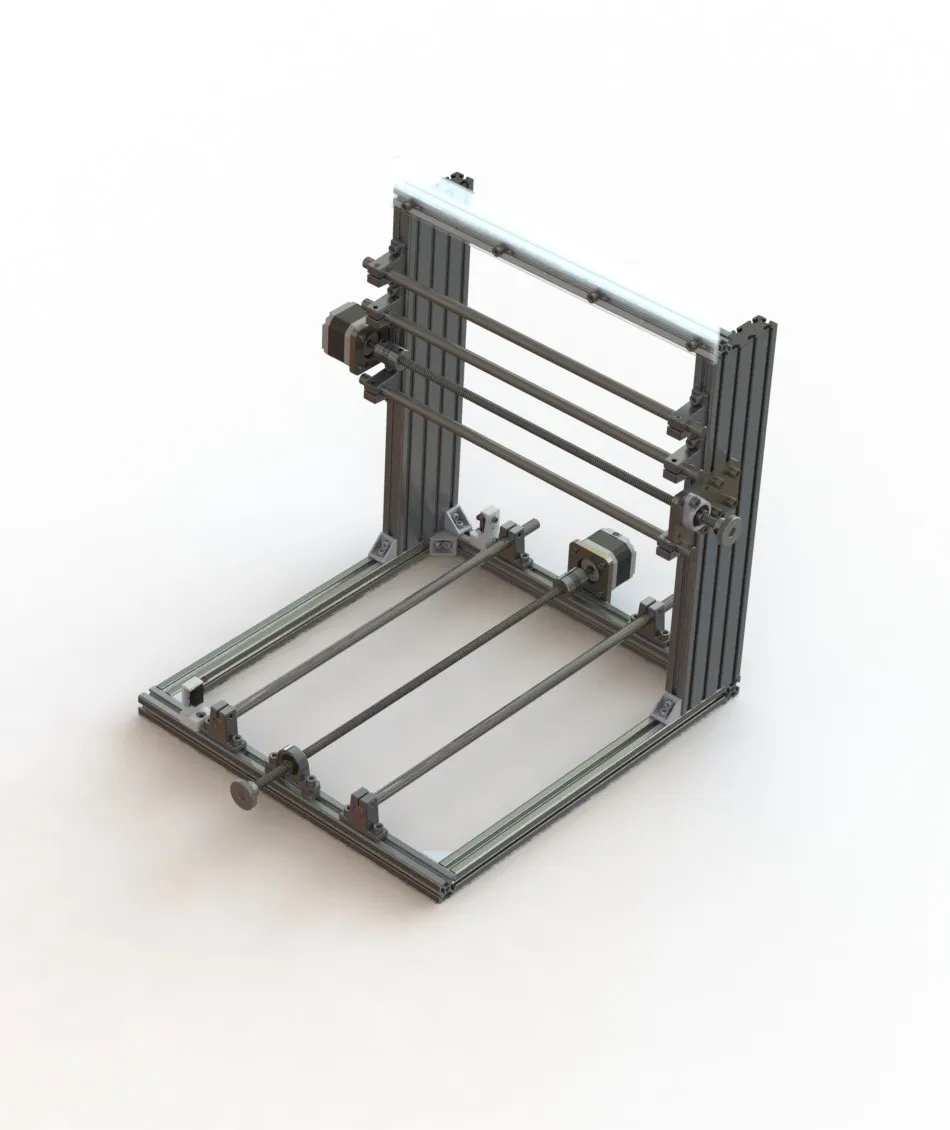
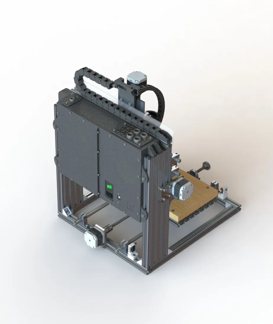
Before any parts were modified or ordered, a full CAD model of the upgraded machine was produced in SolidWorks — covering the frame, all custom fabricated and printed parts, and the motion system assemblies. This allowed fitment, clearances, and mounting geometry to be verified before committing to fabrication.
The rebuild itself followed a clear hierarchy: spindle first, because it was the primary performance constraint, then the mechanical changes that the new spindle forced, then electronics and control to match the rebuilt machine’s capability.
Spindle
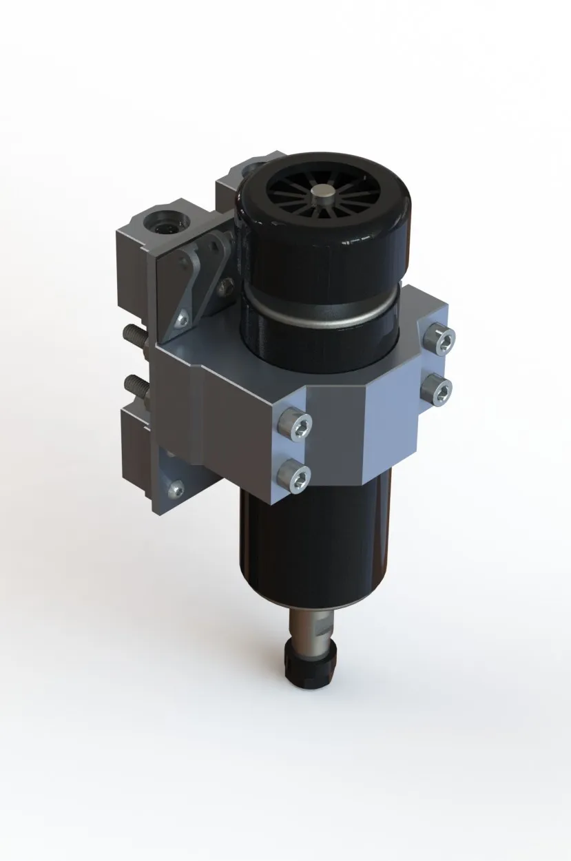
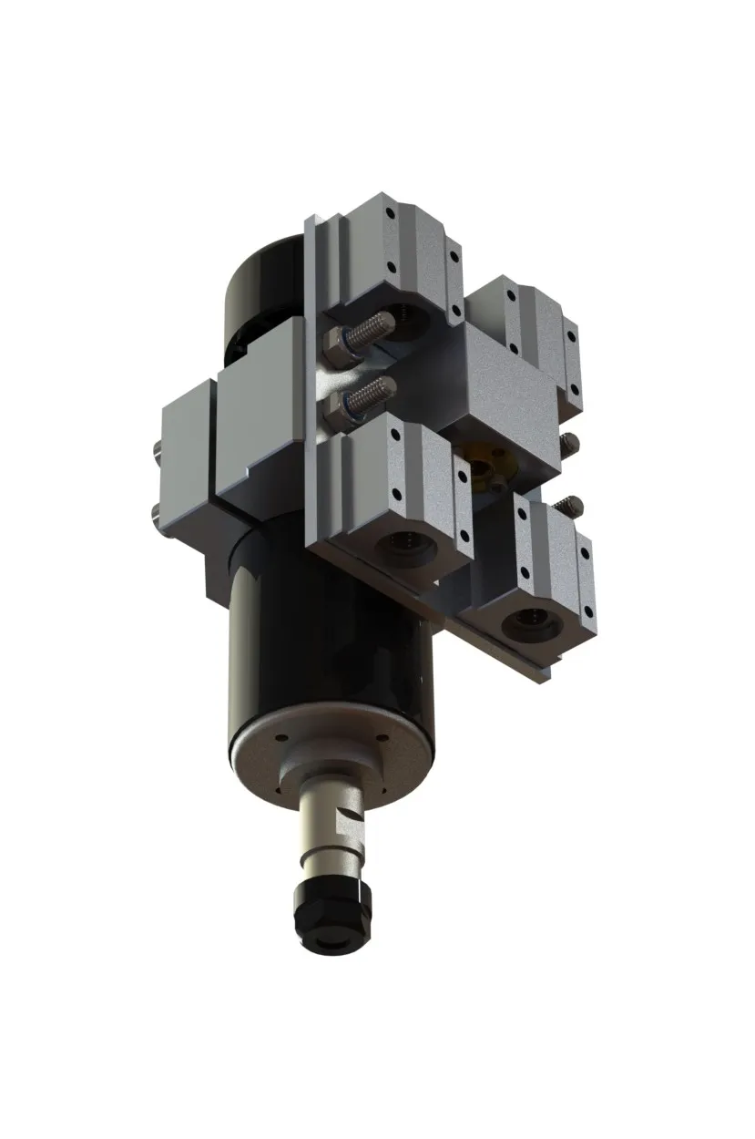
The 775-series brushed DC motor was replaced with a 500W brushless ER11 collet spindle (52mm body) driven by a variable DC motor controller — AC mains input (110–240V), DC 0–100V output, with a front-panel speed potentiometer for manual speed control. The ER11 collet clamps the tool shank uniformly around its circumference via a tapered draw — dramatically better concentricity and retention than a grub screw bearing against a flat shank. The practical result is lower runout, reliable retention under side load, and the ability to run small end mills without tool ejection risk. The new spindle’s mass and cutting forces immediately exposed the inadequacy of the plastic Z axis carriage, making the Z rebuild the direct consequence of the spindle choice.
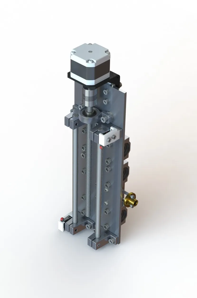
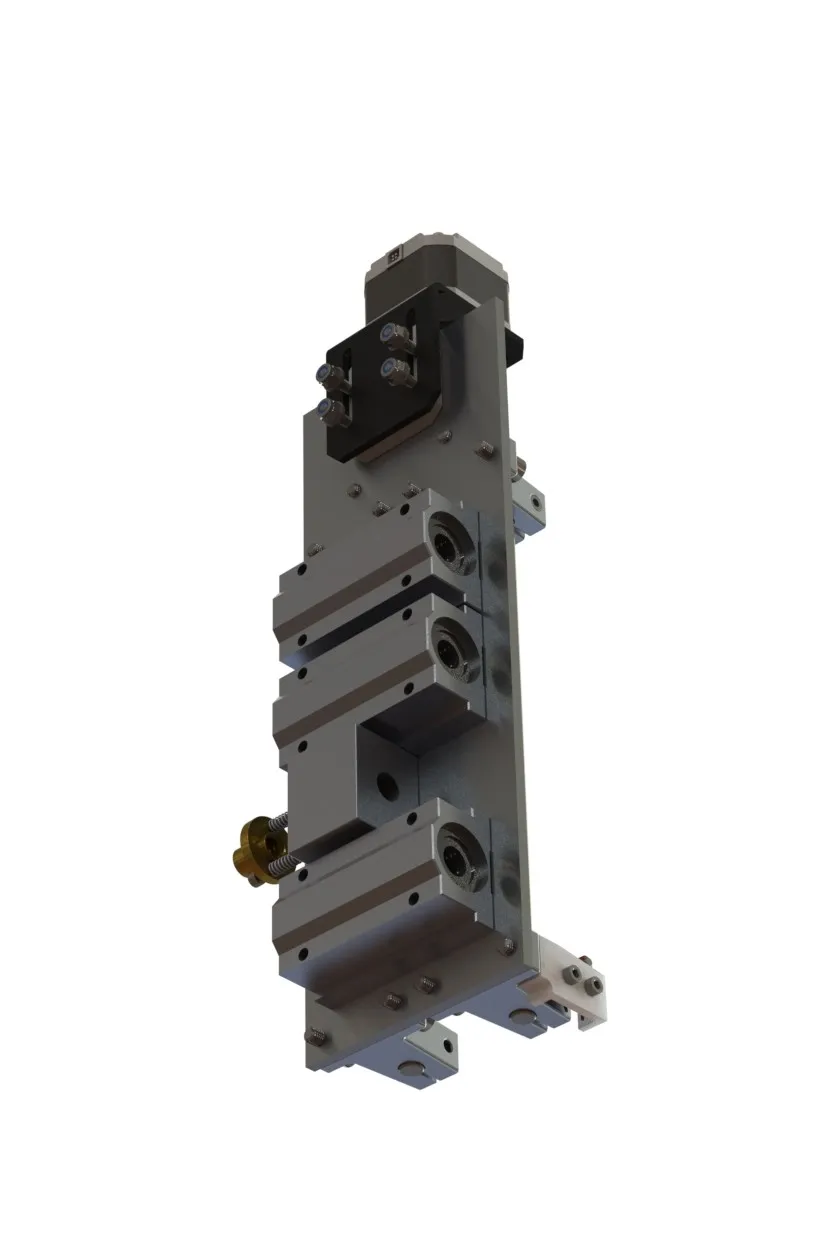
Z Axis
The original NEMA 17 stepper, linear rods, and lead screw were retained — these were not the bottleneck. Everything that held them together was replaced. The printed plastic carriage, motor mount, and lead screw bearing blocks were removed and replaced with custom aluminium sheet metal fabrications. Aluminium replaces the compliance of printed plastic with a rigid load path, eliminating the primary source of chatter under cutting load. The new 52mm spindle clamp integrates into the redesigned carriage. A mechanical limit switch was added on a custom 3D printed bracket, providing a repeatable Z home reference and travel limit. All Z axis cabling was brought into a drag chain.
X Axis
The X axis was modified more substantially than a remount. The linear rod and lead screw positions were relocated from the original kit geometry — which prioritised assembly accessibility — to a layout that improves the moment arm between the cutting load and the linear bearing reaction points, reducing gantry racking under side load. Custom mounting brackets locate the rods and lead screw nut in the revised positions. The motor and bearing mount plates are designed for laser cutting from 6mm steel plate; the current machine runs 3D printed plastic equivalents while the steel parts are pending fabrication. A mechanical limit switch was added for homing and travel limiting, and all X axis cabling was routed through a drag chain.
Y Axis and Frame
The Y axis bearing mounts and lead screw nut hardware were updated to adapt the original linear components to the new T-slot extrusion frame. As with the X axis, the motor and bearing mount plates are designed for 6mm laser-cut steel with plastic prints as stand-ins in the interim. The original kit frame was replaced entirely with a 2020/2080 aluminium T-slot extrusion structure — rigid, square, and reconfigurable as the design evolved during the rebuild. A mechanical limit switch was added for homing and travel limiting.
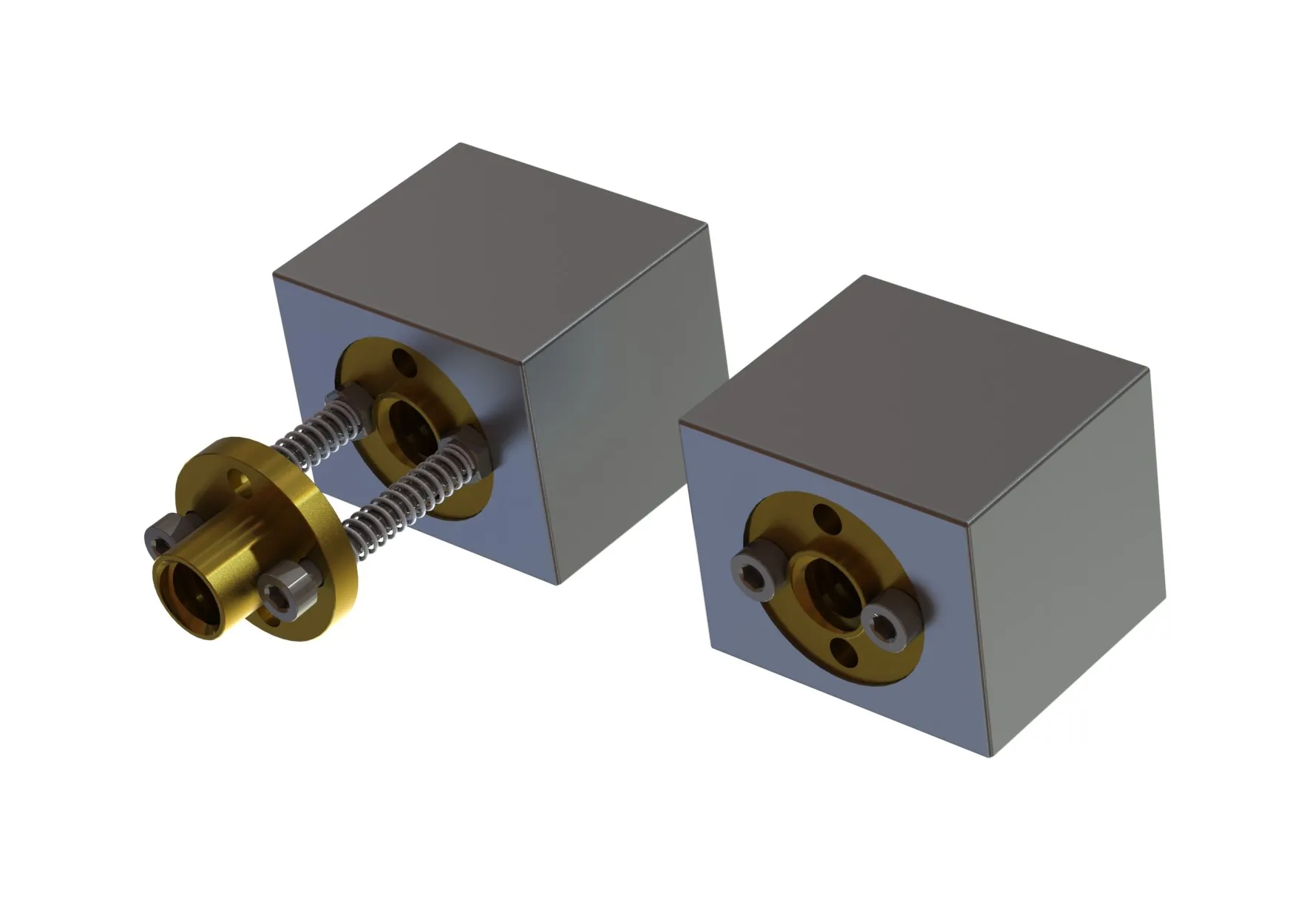
A DIY anti-backlash nut was trialled on both the X and Y axis lead screws, built from spare 3D printer components. Two standard brass lead screw nuts were paired on each lead screw, with a spring fitted onto each of the machine screws that retained them — the springs preloaded the nuts against each other to take up play. The arrangement was removed after evaluation: rather than reducing backlash it introduced additional points where loosening hardware could let play creep in. On a small desktop machine operating under light loads, the residual backlash in a single standard brass nut is not a meaningful constraint, and the simpler arrangement is more predictable.
Electronics and Control
The proprietary kit control board was replaced with an Arduino Uno + CNC Shield v3 running GRBL firmware. This combination provides per-axis steps/mm, acceleration, and velocity configuration; homing cycle support using the mechanical limit switches on all three axes; and work coordinate system (WCS) support for repeatable work zero. GRBL was configured for the machine’s axis parameters — steps per mm calculated from stepper resolution, microstepping setting, and lead screw pitch — then velocity and acceleration limits tuned empirically.
Power is split between two supplies: the spindle motor controller handles the spindle independently; a separate supply powers the Arduino, CNC shield, and steppers. Separating these avoids spindle switching noise coupling into the motion control electronics — a known failure mode on budget machines sharing a single supply. The control electronics and power supplies are housed in a custom enclosure mounted to the rear of the machine frame, with all motor and signal connections brought to panel-mount connectors on the enclosure exterior.
The machine was fully rewired from scratch, all cables re-terminated and routed through the drag chain system.
Outcomes
The upgraded machine cuts light aluminium, hardwood, and engineering plastics where the original could manage only foam and soft timber. Surface finish is observably better, tool retention is reliable, and the machine homes repeatably on all three axes. The improvement is qualitative — validated by cutting results — rather than formally benchmarked.
The machine’s current constraint is scale, not capability: the rebuild reduced the X axis work envelope slightly — from 240mm to 220mm — due to the increased physical size of the redesigned carriages and 52mm spindle body. The 220×170mm work envelope and the original platform’s linear rod diameter set a ceiling on depth of cut and feed rate in harder materials that cannot be overcome without a fundamentally larger machine. For small parts in wood, plastics, and light non-ferrous metals, the upgraded machine performs well within those limits.